

Custom Ceramic Chuck Solutions for Precision Manufacturing and Stable Workholding
2026-09-23
In precision manufacturing, the difference between success and scrap often comes down to one overlooked component: the workholding system. Standard chucks may struggle with delicate or unusual parts, leading to vibration, micro-cracks, or compromised tolerances. That’s where custom ceramic chuck solutions from Semicorex step in. Engineered for stable workholding across demanding applications, these chucks combine advanced ceramic materials with tailored designs to grip parts securely without distortion. Whether you're machining semiconductors, optical components, or advanced ceramics, the right chuck can unlock new levels of accuracy. In this post, we'll explore how custom ceramic chucks from Semicorex address common workholding challenges and elevate your manufacturing process.
Matching Chuck Design to Part Shape Instead of Forcing Stock Options
Standard chucks work fine until a workpiece doesn’t cooperate. Odd boss placements, thin-walled sections, or a profile that tapers oddly can turn a supposedly universal three-jaw into a source of chatter and distortion. Instead of stacking shims or cranking the pressure to compensate, matching the chuck design to the actual part shape gives the clamping force somewhere useful to go. The jaws land where the part can take the load, not where the catalog says they should.
Custom jaw contours and purpose-built chuck bodies sound expensive until you do the math on scrapped parts and extra setup time. A part with an irregular casting or a forged blank rarely sits clean in off-the-shelf serrations. Machining the jaws to match the workpiece profile—even on a modular chuck—cuts down on re-clamping and reduces the need for feeler gauges. It is less about having a fancy tool and more about removing the guesswork from every cycle.
There is also a stiffness payoff. When clamping force follows the part geometry, the cut sees a stiffer loop. Tool life stops dropping off halfway through a batch, and surface finish stops wandering after lunch. If you’re running the same awkward shape week after week, a chuck that mirrors the part pays for itself faster than most people expect, because the machine finally gets to cut instead of fighting the fixture.
Thermal Behavior That Keeps Clamping Force Predictable at High RPM
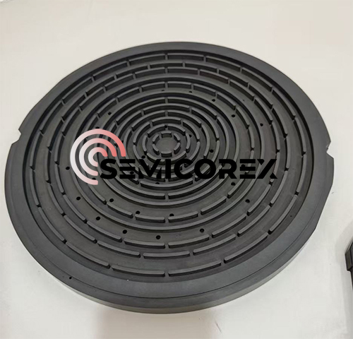
High-speed spindles create a tug-of-war between centrifugal and thermal effects. As rotational speed climbs, the mass of chuck jaws or clamping segments tries to move outward, reducing the radial grip on the workpiece or tool shank. At the same time, heat from bearings and drive components migrates into the clamping assembly. If that heat reaches the interface unevenly, the resulting differential expansion can either exaggerate the centrifugal loss or partially cancel it. A predictable clamp force depends on managing where the heat goes—and how quickly it gets there.
In practice, this means designing the clamping mechanism so that the spindle nose, collet, or jaw carrier expands in a controlled sequence. For example, if the outer housing grows slightly faster than the internal wedge or drawbar, the geometry can tighten just enough to offset centrifugal relaxation. Materials with similar coefficients of thermal expansion are not always the answer; sometimes a deliberate mismatch keeps the contact stress within a predictable window from cold start to full-speed steady state. The goal is not to eliminate thermal drift, but to make it repeatable run after run.
Machine builders often validate this behavior with instrumented test bars that record both temperature and clamping force at multiple speed steps. The data reveals whether the force decay curve flattens out, dips too low, or oscillates during warm-up. A clamp that holds its value within a few percent from 10,000 to 30,000 rpm—without needing frequent re-tightening or compensation—is usually the result of deliberately tuned thermal paths rather than luck.
Ceramic Surface Choices for Grip Without Part Damage
Fine-grained alumina and zirconia remain the most practical starting points for gripping delicate components. Their hardness prevents the surface from embedding debris, but the key is keeping the average roughness below 0.4 µm Ra. At that level, the face still offers enough micro-interlock to hold polished metals or coated glass without leaving witness marks. A slightly porous, unglazed alumina actually works better than a fully dense polished plate, because the pores create local vacuum pockets that raise static friction without increasing contact pressure.
When parts have soft coatings or thin films, switching to a silicon carbide face with a random, non-directional texture avoids the linear scratches that come from ground finishes. The texture should be generated by lapping rather than diamond turning, so peaks are rounded instead of sharp. Pairing this with a shore A 40–50 compliant backing lets the ceramic conform just enough to spread the load, which reduces point loading while keeping the high friction needed for reliable pick-and-place.
For extremely fragile wafers or coated optics, a laser-textured ceramic with isolated dimples rather than continuous grooves provides grip through edge effects while leaving the majority of the surface untouched. Dimples around 50–80 µm diameter and 5–10 µm deep prevent the full-face contact that can trap particles. This style of ceramic works particularly well in dry vacuum environments where suction cups cannot be used and any residual mark would cause immediate rejection.
Production-Run Consistency After the First Hundred Cycles
Early cycles often hide real process behavior. Once a line passes roughly a hundred cycles, thermal expansion, tool wear, and lubricant breakdown start settling into repeatable patterns—but repeatable doesn't always mean stable. Operators who lean on first-run data tend to overcorrect, chasing noise instead of drift. The useful signal at this stage is how tightly cycle times, pressures, and part dimensions cluster, not whether every measurement matches the golden sample.
A practical way to assess consistency is to compare rolling averages in blocks of twenty or thirty cycles. If the mean shifts by more than half the control limit from the first hundred to the next hundred, something mechanical is usually at work—seal compression, die temperature, or feedstock viscosity. Rather than adjust parameters immediately, record the direction and rate of change. Many shifts self-correct once the line reaches thermal equilibrium, and early intervention only adds new variables.
Documentation after the first hundred cycles should focus on range, not just average. Two runs can have identical means but very different spread. Track max-min values for critical dimensions and note any cycle with a slower ejection or higher clamp force. These outliers often predict failures before they show up in scrap rates. Consistency is less about hitting a target every time and more about knowing which deviations are harmless and which ones trend toward a shutdown.
The Difference a Custom Chuck Makes in Final Tolerance Spread
Standard chucks introduce a stack of small errors every time a part is loaded. The jaws grip on generic contact points, the seating varies by a few microns, and that variability feeds directly into the final tolerance spread. A custom chuck designed around the actual workpiece datum eliminates those repeatability losses. Instead of forcing the part to adapt to the chuck, the chuck conforms to the part’s critical features, so the initial positioning error drops to nearly zero before any cutting begins.
For thin-walled or asymmetric components, clamping force is rarely uniform across a standard contact pattern. That uneven pressure distorts the part during machining, and once released, the part springs back into a different shape—widening the tolerance envelope. A custom chuck spreads the gripping load across surfaces chosen to minimize deflection. The result is not just a tighter nominal dimension, but a distribution that stays within a much narrower band after the part leaves the fixture.
Production runs reveal the difference most clearly. With an off-the-shelf chuck, final measurements drift as the insert wears, as coolant temperature shifts, or as raw stock varies within its own tolerance. A custom chuck acts as a mechanical filter, holding the workpiece in a near-identical state every cycle. The final tolerance spread tightens by reducing both the mean shift and the random variation—often enough to bring a process from borderline capability to comfortably within specification without changing the machine tool itself.
Validating Performance Before It Reaches Your Shop Floor
The gap between a promising prototype and a production-ready process can quietly erode margins. Instead of discovering thermal drift, tool deflection, or inconsistent cycle times after fixtures are bolted down, forward-thinking teams now run virtual dry-runs. These simulations push the machine's kinematic envelope, feed it worst-case material batches, and log every axis jerk before a single chip is cut.
That pre-emptive stress test shifts the conversation from "should this work?" to "here's exactly where it breaks." Engineers can then rebalance toolpaths, stiffen weak joints, or derate aggressive feed rates without burning shop-floor hours. The result is a handoff that feels less like a gamble and more like a choreographed rehearsal.
By the time the first real part enters the spindle, operators already know the safe operating window. That confidence is contagious — setups happen faster, quality checks catch fewer surprises, and the line ramps to full rate days earlier than the old trial-and-error rhythm ever allowed.
FAQ
Ceramic materials bring much higher hardness and thermal stability to the table. They resist wear and thermal distortion far better than steel or aluminum, so clamping accuracy holds up over long production runs. That translates directly into tighter tolerances and less downtime for recalibration.
A custom design lets you match the chuck face and clamping zones to the actual workpiece geometry. Instead of relying on generic contact points, the load spreads evenly across the part, which reduces chatter and micro-slippage during machining. The result is a noticeably more stable setup, even at higher spindle speeds.
You see the biggest gains in semiconductor wafer processing, precision optics grinding, and machining of hard or brittle materials. These applications demand extremely flat and clean workholding, often with repeated thermal cycling, where conventional chucks tend to drift or gall over time.
Porous alumina, silicon carbide, and silicon nitride are common choices depending on the job. Alumina offers excellent electrical insulation, silicon carbide adds high stiffness and thermal conductivity, and silicon nitride provides good fracture toughness. The material is selected to balance rigidity, thermal expansion, and wear resistance for the specific process.
With thoughtful structural design and controlled preloading, yes—many ceramic chucks manage irregular shapes and moderate loads without issues. However, they are not intended for violent impact or heavy roughing cuts. For those cases, a hybrid design or a different holding strategy might be more appropriate.
It depends on the manufacturing process, but sub-micron flatness and radial runout are routinely reachable. The key is integrating precision grinding and lapping steps after sintering, which removes residual distortion and brings the working surfaces into exact alignment.
Because ceramics expand very little with temperature change, the chuck maintains its geometry even when the process heats up. That means the clamping force stays consistent and the part doesn't shift microscopically during a long batch. In contrast, metal chucks can loosen or tighten as they warm up.
Start with the workpiece material, dimensions, and required tolerances, then factor in cutting forces, temperature range, and machine interface. Also think about surface finish and porosity if the chuck will be used in a cleanroom or with vacuum holding. Sharing these details early helps avoid redesign loops.
Conclusion
A custom ceramic chuck starts where standard workholding stops. Rather than asking a part to fit an off-the-shelf clamp, the chuck face is contoured to the actual geometry—whether that means a thin-walled ring, a tapered hub, or an asymmetric casting. This removes the usual compromise of packing stock options with shims or soft jaws that drift. At high spindle speeds, the ceramic body and its mounting interface are selected for predictable thermal growth, so clamping force stays steady instead of loosening or over-tightening as heat builds. The grip surface itself can be tuned from a fine ground finish to a lightly textured contact patch, giving secure holding on polished or coated parts without leaving marks, scratches, or micro-fractures.
That stability shows up over long production runs. After the first hundred cycles, a well-matched custom chuck does not break in unpredictably; repeatability remains tight because the contact area and expansion path were designed for the specific workpiece, not borrowed from a general-purpose catalog. The measurable effect is a narrower final tolerance spread on turned, milled, or ground features, often cutting scrap and rework that generic clamping quietly introduces. Before any of this reaches a shop floor, performance is validated on a test stand with the customer's part data—runout, gripping force, and thermal drift are checked at operating rpm. The result is a workholding solution that behaves the same on day one and day one thousand.
Contact Us
Contact Person: Svenja Wei
Email: [email protected]
Tel/WhatsApp: +8613567891907
Website: https://www.semicorex.com