

ODM Louver Damper Valve Options That Deliver Precise Airflow Control in Industrial Systems
2026-11-21
Most airflow control problems in industrial systems aren’t caused by undersized fans or poor duct layout—they start at the damper. Louver designs that drift, leak, or lose repeatability under pressure quietly erode performance. ODM louver damper valve options that deliver precise airflow control in industrial systems change that dynamic. We’ll break down the valve configurations, seal materials, and actuation choices that actually hold up in demanding processes, and show where THT addresses the failure points generic dampers ignore.
How Multi-Blade Damper Valves Handle Uneven Airflow Across Wide Ducts
In wide ducts, airflow rarely arrives evenly. A nearby elbow, a sudden transition, or a loaded filter bank can leave one side of the duct moving fast while the other side barely moves. A single-blade damper only pivots near its center, so it tends to throttle the middle of the airstream and leave the outer edges largely undisturbed. Multi-blade damper valves change that behavior by splitting the duct cross-section into several narrower lanes. Because each blade sits in its own lane, local velocity differences can be handled with local adjustment instead of one blunt correction applied across the full width.
The linkage pattern also plays a role. Opposed-blade arrangements rotate adjacent blades in opposite directions, which helps straighten skewed flow and push air toward the slower side. Parallel-blade arrangements move each blade in the same direction and can shift the air path without creating a hard pressure drop at one edge. On wider ducts, some assemblies allow individual blade trim or use blades of different widths, so the outer lanes can open slightly more or less than the center. That fine-tuning is what keeps the downstream velocity profile from looking lopsided.
The practical effect is less turbulence and a steadier pressure reading across the face of the duct. Downstream sensors, coils, and filters see a more even approach, which reduces hunting in control loops and avoids premature loading on one side. Rather than treating uneven airflow as a single blockage to be choked off, multi-blade dampers shape the velocity profile in smaller increments, which matters most on ducts wide enough that one side can act almost independently from the other.
What Separates a Low Leakage Louver Damper From a Standard One
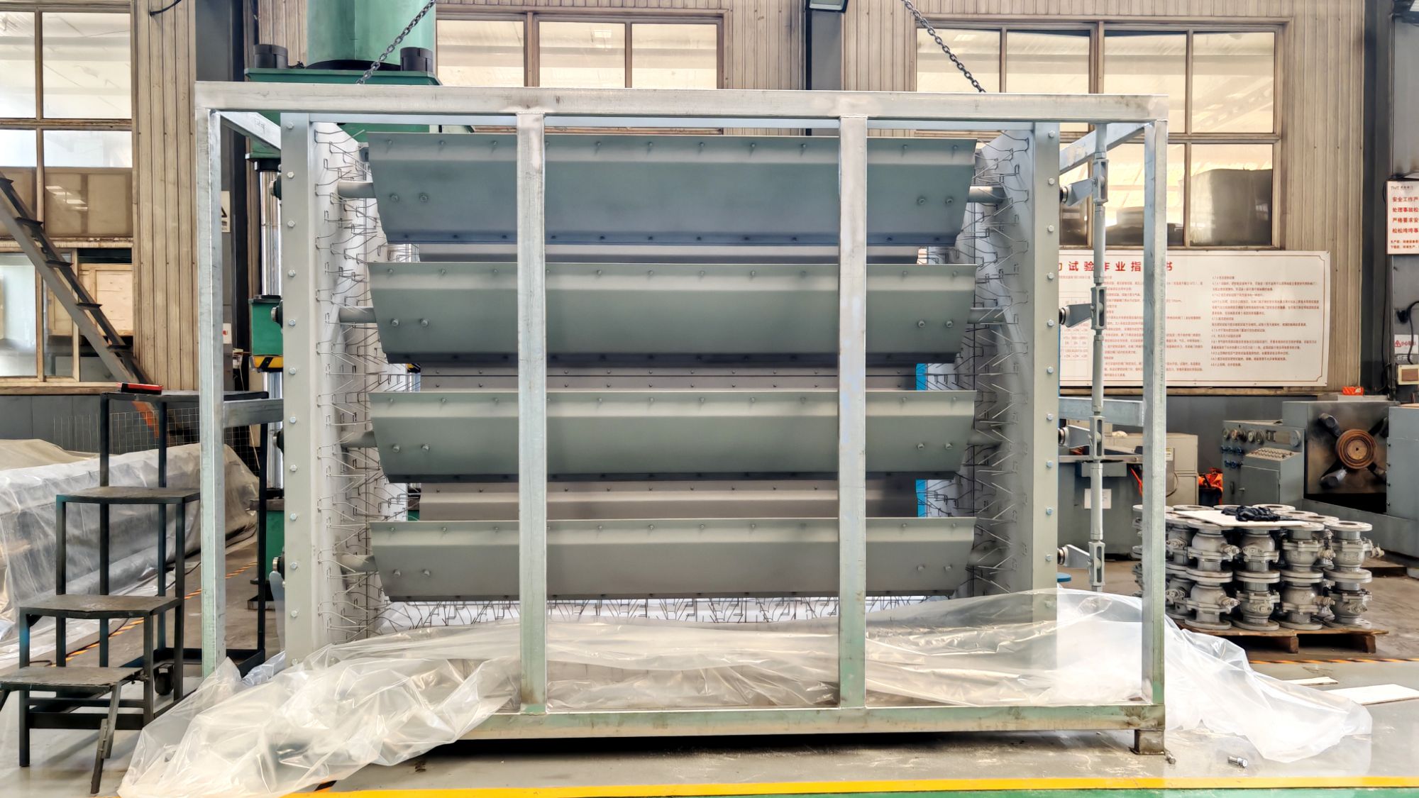
Most dampers promise to stop airflow, but the gap between a standard unit and a low leakage louver damper shows up in the details that get overlooked on a spec sheet. A conventional damper commonly relies on simple blade edges and basic seals, which leave small but persistent paths for air to slip through when the system is under static pressure. Over time, thermal expansion, vibration, and everyday wear make those paths wider. Low leakage designs attack the problem at the joints and bearings, using compressible seals, blade-to-blade nesting, and frame gasketing that stay tight even after thousands of open-close cycles.
The testing standard tells the real story. While a standard damper might be rated only for a broad leakage class that allows a noticeable amount of bypass airflow, a low leakage louver damper is typically built to meet a stricter leakage class under ASTM or AMCA conditions, often at higher differential pressures. That translates to better zone isolation, less energy pulled from conditioned spaces, and fewer drafts in occupied areas near the duct termination.
Construction choices also drive the difference. Low leakage louver dampers tend to have heavier-gauge frames, stainless steel edge seals, and mechanically fastened blade tips rather than relying on a simple interference fit. Standard units often prioritize low initial cost, accepting some leakage as a tradeoff. In contrast, low leakage versions earn their place in systems where air balance, humidity control, and pressure differentials cannot be compromised.
Why Damper Blade Profile Changes Control Behavior More Than Size
Blade profile shapes the pressure distribution across the face of the damper, and that pressure distribution is what determines how flow responds at partial travel. A flat blade tends to push the separation point toward the edges early, giving a sharp initial response. A cambered or tapered blade, however, can keep the airstream attached longer and move the separation point gradually, so the same angular movement produces a smoother and more deliberate change in flow. That shift in attached flow matters more than simply adding surface area, because it rewrites the relationship between blade position and flow rate.
Size tends to scale the capacity envelope. A larger damper can handle more total air volume and may require more actuator torque, but the underlying control curve often remains similar to that of a smaller unit with the same profile. Changing the blade cross-section, even by a few degrees of leading-edge angle or a small alteration at the trailing edge, moves the entire operating curve. It can make the damper more authoritative in low-flow conditions or soften its authority at mid-stroke without changing the nominal diameter.
That separation between capacity and control shape is easy to miss when comparing datasheets, because nominal size is visible and profile details are subtle. In practice, two dampers with the same face dimensions can deliver noticeably different room-side control behavior if one uses a flat blade and the other uses a contoured blade. The profile sets how turbulence forms, how pressure recovery happens, and how much force the actuator sees at partial openings. Size mostly decides how much air the assembly can pass; the profile decides how that air is metered.
Frame and Flange Options That Avoid Ductwork Modifications
Many air handling units ship with standard frame depths and flange patterns that assume a specific duct size and connection style. When your existing ductwork was built around older equipment or a different manufacturer's dimensions, the last thing you want is to cut, patch, or rebuild sections of metal just to make the connection work. A better approach is to look for frames and flanges that match the duct's actual opening rather than forcing the duct to match the unit. This often means using a wider flange face, an offset frame, or a slip-on connection that can absorb small dimensional differences without field modification.
The real advantage shows up in retrofit jobs where downtime is tight and existing duct hangers, access doors, or fire dampers are already in place. Instead of reworking the duct, you can select a flange with a slotted hole pattern that allows lateral adjustment, or a frame with a removable corner section that drops in around the existing duct flange. Some configurations even include an integrated canvas connector or a double-flange design that bridges a gap between the unit outlet and the duct collar. These options keep the duct untouched, preserve its static pressure characteristics, and avoid creating new leak points where sections were cut and rejoined.
It is worth confirming the exact dimensions of the existing duct before ordering, because not all "standard" flanges are actually standard across brands. Measure the inside and outside duct dimensions, the bolt hole spacing, and the distance from the unit opening to the nearest duct support. With those numbers, a supplier can often provide a frame that aligns without any notching or trimming. In many cases, a custom-punched flange costs far less than the labor and materials involved in modifying ductwork on site, and it keeps the installation clean enough to pass an air-balance review without extra sealing work.
Actuator Sizing Rules for Louver Dampers That Run Continuously
Something people miss with louver dampers that never stop moving is that heat buildup, not just peak torque, determines whether the actuator survives. Start by confirming the manufacturer allows 100% duty cycle under your actual ambient temperature. A unit rated for intermittent duty may deliver the same torque on paper but overheat when it holds a position or makes constant corrections for hours. If the datasheet gives a maximum continuous run time, a motor temperature class, or a cycles-per-hour limit, read those as fixed boundaries. Also check the enclosure rating and mounting orientation, because heat can pool around the motor when the unit is installed against a hot duct or under a rooftop cover.
Torque selection for these dampers should come from the pressure drop across the blade assembly, not from a generic duct area calculation. Seals, side channels, bearings, and blade edges all add friction, and that friction changes with blade angle. Over time, dust and slight linkage wear push the required torque higher, so a multiplier of 1.3 to 1.5 over the worst-case calculated load makes sense. If the blades sit directly in an airstream or work against outdoor wind, use the upper end of that range and verify the actuator can hold position at both ends of travel without hunting.
A continuously modulating damper may spend most of its life making small corrections near one position, which is harder on the gear train and motor insulation than occasional full strokes. Look for an actuator with electronic overload protection, a high enough total stroke life, and a control profile that allows a deadband or slow positioning to cut down unnecessary movement. If the position must be held during a power failure, choose a fail-in-place or manual override unit rather than a spring return model, since spring return actuators are generally not built for constant modulation and may overheat or wear prematurely.
Preventing Corrosion and Binding in Dampers Exposed to Wet Process Air
Dampers handling wet process air often face two connected problems: corrosion on metal surfaces and binding at moving joints. Moisture combined with chemical carryover from upstream processes accelerates oxidation, while mineral deposits or swollen seal materials can restrict blade movement. When a damper binds, operators tend to force it open or closed, which worsens wear at the pivot points and may distort the blades. Over time, this leads to poor airflow control, leakage past the closed damper, and unplanned downtime for repairs.
A practical approach starts with material selection, but it does not end there. Stainless steel shafts and blades resist many corrosive environments, yet crevices between dissimilar metals or between the blade and its seals still trap moisture. Using bushings made from engineered polymers instead of metal lowers friction and eliminates one common corrosion site. Drainage matters just as much as metallurgy: the damper frame should allow condensate to leave instead of pooling near the lower bearings. Shaft seals kept slightly away from the blade edge can also reduce the wicking effect that draws moisture into the bearing housing.
Maintenance routines often fail because corrosion and binding are treated as separate issues. A better schedule checks blade torque at multiple positions, not just fully open and fully closed. If higher torque appears only in the mid-stroke, deposits are likely building on internal stops or linkage arms. Cleaning with low-pressure water followed by a dry wipe usually restores movement without pushing abrasive particles deeper into seals. When persistent binding returns quickly, the root cause is frequently a misaligned actuator rather than the damper itself, so verifying actuator travel and linkage geometry should happen before replacing bearings or seals.
FAQ
Louver dampers tend to handle wide duct sections with less flow disturbance because the blades spread the air instead of forcing it around a single disc. That usually means a lower pressure drop at high flow and more predictable control as the damper opens.
Opposed blades are generally the better starting point for low-flow control. They create a more even velocity profile and reduce the sudden jump you can get with parallel blades just off the closed position.
It affects the result more than most people expect. An undersized actuator or sloppy linkage will make even a well-built damper hunt and drift. The torque should be checked against the closed-blade pressure drop, not just the open duct pressure, and direct-coupled mounting helps keep lost motion down.
For corrosive exhaust, 316 stainless blades and frames are common, but the alloy should match the exact chemistry. For high-temperature service, a carbon steel frame with stainless blades and high-temp shaft bearings is often a better value than building everything from stainless.
A heavy-duty parallel blade design with a flexible or notched seal edge tends to last longer in dirty air. The blades can close with more clearance to scrape past dust and debris, whereas tight-sealing opposed blades may bind or wear the seals quickly.
A control damper is built for continuous throttling, so it needs tighter bearings, less hysteresis, and a stable actuator mounting. An isolation damper is meant for occasional open or closed duty and usually gets a higher leak class. Using an isolation damper for modulation can wear the seals and linkage out quickly.
Custom frame depth to match the existing flange gap, extended shafts for insulated duct walls, and analog position feedback are usually the upgrades that matter. Swapping blade seals and using a characterized actuator can also correct poor low-flow behavior without changing the entire duct layout.
Yes, an ODM setup can follow your frame dimensions, blade design, coating, seals, and actuator package under your own part number. The key is to provide the operating pressure, temperature, direction of flow, and control signal so the damper is matched to the system rather than pulled from a generic catalog drawing.
Conclusion
In practice, precise airflow control across wide ducts rarely comes from a single oversized damper. Multi-blade louver damper valves split the face area into narrower sections, which helps flatten velocity profiles and prevents the corner starvation or center-heavy flow that undermines balance in large industrial ducts. What often matters more than nominal size is blade profile. A curved or airfoil-shaped blade changes the relationship between stroke and flow earlier in travel, giving finer modulation where it counts, while flat blades tend to behave more like on/off devices until nearly closed. Low leakage construction is not just a gasket upgrade; it depends on edge seals, blade stops, and frame rigidity working together so closed positions remain tight under differential pressure.
ODM options also reduce installation and maintenance friction. Frame and flange choices can match existing duct dimensions and bolt patterns, avoiding field modifications and keeping retrofit schedules short. For dampers that run continuously, actuator sizing should account for torque at the highest anticipated pressure drop, not just free-air movement; a conservative margin prevents hunting, overheating, and premature wear. In wet process air, corrosion and binding are common failure points, so material selection, shaft seals, bearings, and drain paths need to be considered together. Stainless or coated blades, non-metallic bearings, and sloped frame channels help keep movement free and repeatable. These details, when selected as a package, deliver the control stability that generic damper valves usually miss.
Contact Us
Contact Person: Su Zhang
Email: [email protected]
Tel/WhatsApp: +86-25219206
Website: https://www.tht-valve.com/