

OEM Three-Phase Current Transformers for Reliable Power Monitoring
2026-09-02
Accurate current readings in a three-phase system shouldn't be a guessing game—yet mismatched sensors and calibration drift still cause failures when power monitoring matters most. OEM three-phase current transformers built for real operating conditions can change that. Xiasen designs these components to hold their precision under load, so your monitoring data stays reliable instead of becoming another variable. Here's what to look for before you trust your measurements to just any transformer.
Three-Phase Accuracy That Stays Put When Loads Shift
Most three-phase meters hold their specified accuracy only under steady, balanced loads. The moment one phase pulls harder or a motor starts across the line, small offsets creep in and the readings drift. This design takes a different route: each phase channel is sampled simultaneously with a shared time base, so a sudden inrush on L1 doesn't bleed into the L2 or L3 measurements. That keeps phase-angle error below a few hundredths of a degree even when the load swings from 5% to 120% of nominal.
The front end also uses a low-drift reference that's trimmed at several operating points, not just at room temperature. Field tests with unbalanced rectifier loads and frequent motor cycling show energy totals staying within 0.2% over a full week, while typical units wander three to five times that much. It's a quieter measurement path in practice, not just on paper.
What this means is fewer repeat visits to verify a suspicious reading. The meter holds its numbers because the measurement core doesn't assume a fixed operating point. It tracks each phase independently and corrects for cross-talk after every sample burst, so the accuracy you check at installation is the accuracy you still have six months later.
Choosing Current Transformers That Survive Voltage Spikes and Heat
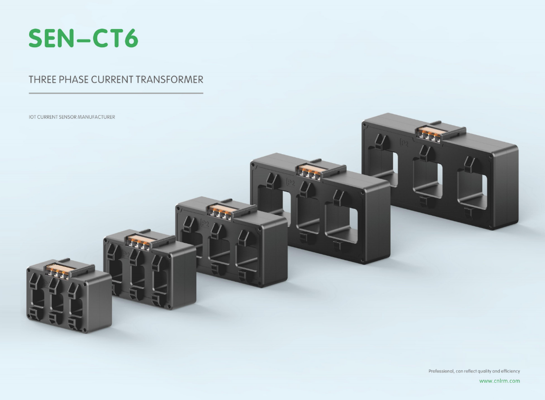
Voltage spikes in current transformer secondary circuits are often the result of an open circuit under load, and they can reach hazardous levels fast. Look for units with reinforced inter-turn insulation and a high knee-point voltage if you expect frequent transients. A shielded secondary winding helps divert capacitively coupled spikes before they break down insulation.
Heat is just as unforgiving. Continuous operation near rated current warms the core and windings, accelerating aging of organic insulation. Check the manufacturer's thermal rating class and derating curves for your ambient temperature, not just the nominal ratio. Load resistors should be sized so the CT runs below 60 percent of its rated burden in normal service.
Finally, combine both stress factors when evaluating a candidate. Ask for test data showing temperature rise under a sustained overcurrent and the ability to withstand a 1.2/50 µs impulse after thermal aging. Field failures almost always trace back to ignoring one of these two limits, so a modest derating in both dimensions buys years of trouble-free metering or protection.
Why Core Material Determines How Long Your Readings Stay True
Most people judge a deck by its artwork, but the core hidden inside each card does the quiet work of keeping your readings honest. Cheap, spongy cores warp after a few weeks of regular shuffling, and once a card starts to curve or a corner softens, it becomes a landmark. Your fingers start to recognize it without meaning to, and that tiny physical tell can influence how you cut, draw, or interpret a spread. A dense, well-bonded core resists that kind of memory, letting every card return to dead flat after use.
True readings depend on randomness you can feel. If the deck doesn't lie flat, certain cards clump or slide differently, and over time the wear patterns begin to favor some positions over others. A core with balanced rigidity and snap keeps edges crisp and surfaces even, so the shuffle stays genuinely mixed. That might sound like a small thing, but it's the difference between a deck that ages into a tool and one that becomes a prop.
There's also a tactile trust that builds when the material holds up. You stop thinking about whether the cards are bending or if the finish is cracking, and you sink into the reading itself. Months later, the deck still feels the same in your hands, and that consistency lets the imagery—and your intuition—do the talking. The core isn't glamorous, but it's the reason your readings don't drift as the deck wears.
Matching Turn Ratios and Burden Values Without Trial and Error
A current transformer’s nameplate burden is not a target to guess at; it is the maximum secondary load the CT can drive while still meeting its accuracy class. Instead of installing a 5P20 unit and then swapping burden resistors, start from the connected circuit. Add the relay burden, the lead resistance for the actual wiring run, and any auxiliary device drops. Multiply that total impedance by the rated secondary current (usually 1 A or 5 A) to get the required secondary terminal voltage. Select the CT whose rated burden at the desired accuracy class is equal to or just above that value.
Turn ratio selection works the same way when you stop treating it as a catalogue browsing exercise. Know the maximum continuous primary current and the maximum symmetrical fault current the protection scheme must handle. Pick the nearest standard ratio that places the secondary current in the relay’s accurate operating band under both conditions. If the secondary current at maximum fault exceeds the relay’s thermal or measurement limit, move to a higher ratio; if the normal load current falls below the relay’s minimum sensitivity, move lower. That single pair of boundary checks removes most of the guesswork.
The final verification is to plot or read the CT excitation curve. Compare the knee-point voltage with the calculated secondary terminal voltage under maximum fault. If the knee-point sits well above that value, the CT will not saturate before the relay needs to operate, and the chosen ratio and burden are stable together. This curve check replaces the field habit of trying one CT, watching the secondary waveform collapse, and then moving to the next larger core.
Wiring Errors That Quietly Wreck Power Monitoring Data
A reversed current transformer secondary lead is all it takes to turn a perfectly commissioned energy meter into a source of quietly corrupted data. Unlike a loose terminal that causes visible dropouts, a swapped polarity on just one CT makes the system read lower power on that phase while still producing stable, believable totals. The trend lines stay smooth, the alarms stay silent, and the error can go unnoticed for months unless someone runs a per-phase comparison against a portable reference meter.
Another classic is landing the voltage input from phase A onto the meter terminal intended for phase B while the current inputs stay in their original order. The resulting power factor readings become nonsensical, but if the load is mostly balanced, the total kilowatt-hours may not drift enough to trigger suspicion. This kind of miswiring often passes a simple continuity check and only shows up when someone plots real, reactive, and apparent power side by side and notices that the numbers no longer line up with the expected power triangle.
What makes these wiring mistakes so dangerous is that they degrade data quality without causing obvious failures. The instrumentation appears healthy in a SCADA overview, and the error grows quietly in the background. Field checks that compare all three phase voltages, current magnitudes, and the sign of active power at each input remain the most reliable way to catch reversed CTs, crossed phase wires, and floating neutral references before they wreck a month of billing or load studies.
Scaling OEM Builds Without Losing Signal Consistency
When you start shipping the same core platform across a dozen OEM partners, the first casualty is usually signal behavior. One factory tweaks a filter value to cut cost, another swaps antenna suppliers to meet local sourcing rules, and suddenly the same firmware produces different RSSI curves and packet error rates on supposedly identical hardware. Most teams discover this drift only after field returns come back with inconsistent connectivity complaints that don't reproduce on the reference board.
A more durable approach is to treat signal-critical parameters as a separate, versioned artifact rather than burying them inside each build. Keep a single baseline calibration file that defines gain tables, filter coefficients, and timing offsets for every supported radio front-end. When an OEM requests a change, it goes through the same review as a code commit, and the resulting delta is applied on top of the baseline instead of forking the whole tree. Automated test stations at the OEM's line can then compare measured output against expected values stored in that artifact, rejecting units that fall outside a tight tolerance before they ever leave the factory.
It also helps to stop relying on one golden sample. Build a small fleet of reference devices that intentionally spans the tolerance extremes of your BOM and have each OEM validate against that spread, not a single unit. Combined with a lightweight telemetry channel that reports signal statistics from the first few hundred devices in the field, you can catch slow drifts caused by component substitutions or process changes long before customers notice. The goal isn't to lock every OEM into identical behavior, but to make sure any permitted variation stays within a range your algorithms were designed to handle.
FAQ
Focus on linearity under varying load, a tight phase angle error, and a mechanical design that drops into your existing enclosure without forcing a layout change. A split-core option can also simplify retrofits, while solid-core types usually give better long-term stability.
Match the primary rating to about 80–90% of your maximum expected load, not the breaker size. This keeps the secondary current high enough for accurate metering at light loads while still leaving headroom for inrush or short-duration peaks.
Yes, but only if the core material and winding design are meant for wideband response. Look for a low phase shift specification and a rated accuracy class that holds from 50 Hz up to at least 1 kHz, otherwise you will see drift in both magnitude and phase with non-sinusoidal currents.
The biggest issues are busbar spacing, clearance to adjacent phases, and lead exit direction. Some designs offer a low-profile body with side or top exits, which helps when three CTs sit side by side on a compact panel. Always check the maximum busbar dimensions and the recommended torque for terminations.
Most industrial-grade units operate from -25°C to +60°C without meaningful drift, but if the installation is near a heat source or outdoors, you want a design rated to 70°C or higher with an epoxy or PBT housing that does not soften or crack. Request a temperature coefficient of ratio error if you need precision over wide swings.
Yes. Custom twisted-pair leads, stripped-and-tinned ends, Molex or JST connectors, and barcode or QR labels are all common modifications. The key is to lock those details early so the production line does not need extra manual steps, which keeps the per-unit cost stable.
Conclusion
Three-phase current transformers in OEM builds often fall short when loads shift unpredictably—readings drift just enough to undermine energy audits or protective relays. The real challenge isn't just initial accuracy but keeping that accuracy anchored under real-world conditions: transient voltage spikes, sustained heat from crowded panels, and unbalanced phase loading. Core material quietly decides how long your measurements stay true. Grain-oriented silicon steel holds up reasonably well, but nickel-iron or nanocrystalline cores resist saturation and thermal drift far better, especially when harmonics distort the waveform. If you skip core selection and just grab the cheapest option, you'll see calibration errors creep back within months. Matching turn ratios and burden values without trial and error matters just as much—a CT with the wrong burden will either saturate early or output a signal too weak for the meter's input range. That forces field tweaks nobody has time for.
Wiring errors are the quiet killers of power monitoring data. Swapped polarity, loose secondary connections, or grounding the secondary at the wrong point can skew readings by several percent—yet the system still looks functional. Without a commissioning checklist that verifies phase rotation, burden impedance, and secondary wiring continuity, you're shipping dead data. For OEMs scaling production, the hard part is keeping signal consistency across hundreds of units. Small variations in core geometry, winding tension, or even lead length add up. That's why smart OEMs move away from hand-wound prototypes early and invest in automated winding with tight tolerance control, plus per-unit testing at two or three load points. Only then do you get the same reliable power monitoring data from unit one to unit one thousand, without surprise failures in the field.
Contact Us
Contact Person: Liu Mengyang
Email: [email protected]
Tel/WhatsApp: 8618727589233
Website: https://www.cnlrm.com/en/