

Professional IMS Core Network Design Essentials for Reliable Voice and Multimedia Services
2026-11-18
Most IMS core discussions stop at architecture diagrams. The hard part is making sure a network still delivers clear voice and stable multimedia when signaling loads spike or a media path reroutes mid-call. That reliability doesn’t come from adding more boxes—it comes from design choices that anticipate failure, manage latency, and keep session control predictable. In this post, we break down the essentials that matter in production: CSCF placement, diameter routing, QoS boundaries, and redundancy models that hold up under real traffic. Whether you’re modernizing an existing core or planning a greenfield rollout, the goal is a service subscribers trust without thinking about it. Platforms like IPLOOK show how these principles can move from theory into deployable, carrier-grade infrastructure.
CSCF Placement and Call State Replication
Where a Call Session Control Function sits within the IMS topology shapes how reliably it can preserve call context. In distributed deployments, the CSCF is often placed close to the access edge so that signaling latency stays low and local policy can be applied before traffic heads deeper into the network. This positioning introduces a practical constraint: call state that lives only on a single node becomes a single point of failure the moment that node restarts or loses connectivity. Operators therefore tend to pair edge placement with some form of state redundancy, even if the replication scope is deliberately narrow.
Call state replication across CSCF instances typically focuses on the session data that matters for continuity, such as dialog identifiers, registered contact bindings, and the sequence numbers used for SIP transactions. Rather than copying every transient timer or parsed header, mature designs replicate only the minimum set needed to let a sibling instance take over without forcing endpoints to re-register or re-establish mid-call signaling. The replication interval can be synchronous for critical transitions or asynchronous for less volatile data, and the choice usually depends on how tolerant the deployment is to stale state during a failover.
A less obvious consequence of CSCF placement is how replication traffic competes with live signaling on the same interfaces. When state updates are sent between sites, they can momentarily consume bandwidth that would otherwise carry INVITE or SUBSCRIBE messages. This pushes some operators toward local clustering within a single site for high-frequency changes, while keeping geographically distant replicas only for disaster recovery. The end result is a layered approach where normal failures are absorbed by a nearby peer and larger outages rely on a slower but broader state copy.
Diameter Signaling Without Single Points of Failure
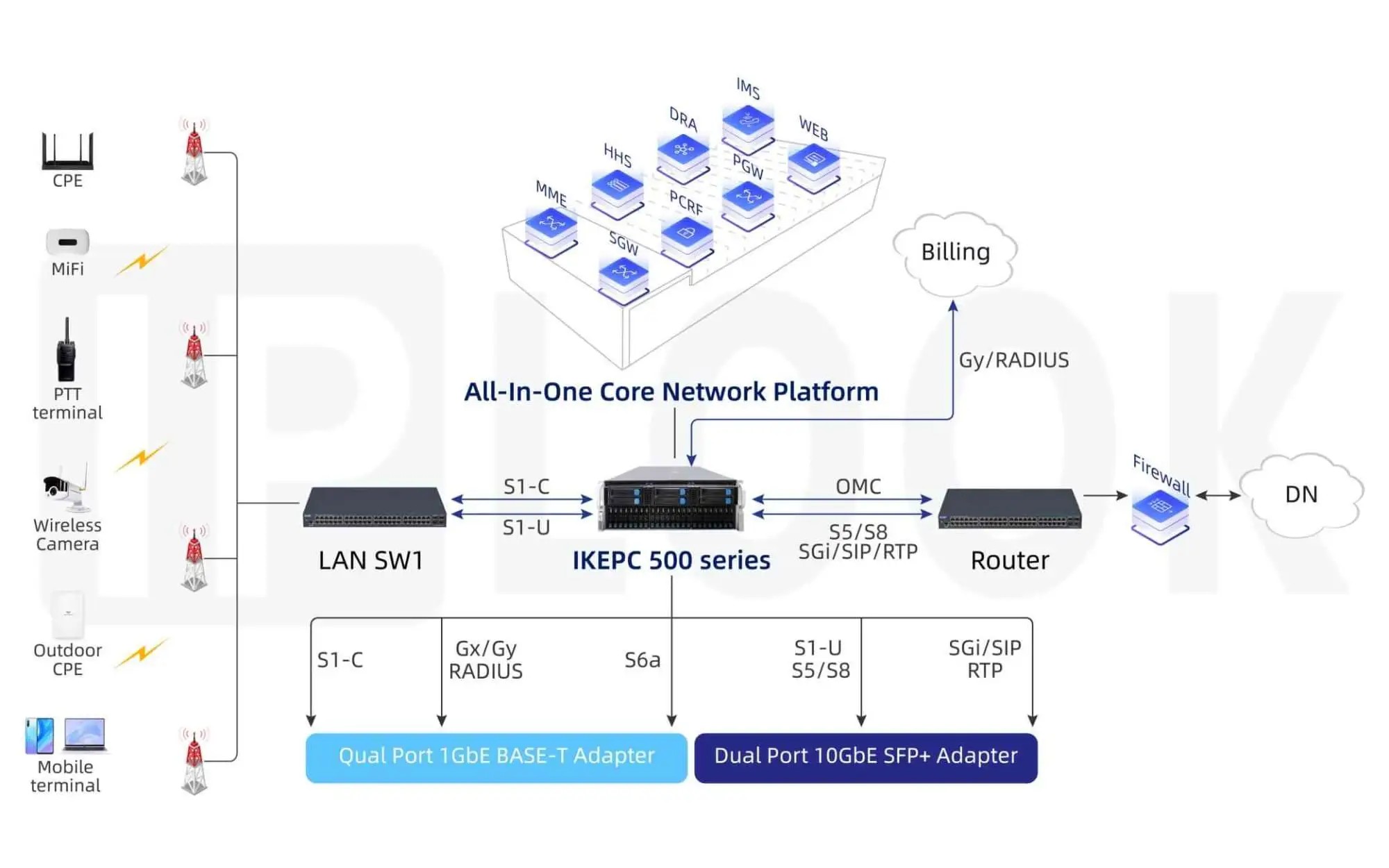
Designing Diameter signaling paths without a single point of failure means moving past the idea that one standby box can cover a primary fault. In the control plane, a lost peer is not just an idle connection; in-flight authentication, policy, and charging transactions can stall. Multi-homed SCTP associations between every critical peer give the transport layer a fast path for switching to a secondary link, while application-level retries and failover logic keep pending sessions from being silently dropped.
Routing agents often get treated as a natural aggregation layer, but that can create a hidden choke point. Instead of funneling all traffic through a single DRA site, deployments can maintain active Diameter connections to two or more DRA nodes and let selection rely on per-request keying, such as IMSI ranges, combined with dynamic health checks. This prevents a routing tier outage from taking down entire services even when lower-layer redundancy is already in place.
Operationally, the harder part is keeping failover behavior honest. Peer state tables, capability exchanges, and watchdog timers have to stay consistent across sites; otherwise a node may route to a peer that no longer advertises the required application and create a signaling black hole. Regular DWR/DWA probing, combined with centralized but replicated configuration, lets the network detect partial failures quickly and redistribute traffic before call setup or data session establishment is visibly affected.
Session Border Control Policies That Protect Real-Time Media
Session border control policies do their most valuable work after call setup. Signaling checks may allow a call, but media policies determine whether the RTP stream itself is allowed to cross a network boundary. A common approach is to anchor media on the SBC, forcing audio and video through a controlled relay rather than allowing endpoints to exchange packets directly. Combined with latching, which locks a session to the first IP and port pair that sends valid RTP, this keeps media from being redirected mid-call to an attacker-controlled address.
Beyond anchoring, policies have to treat real-time media as an attack surface. Rate limits tied to call state help discard RTP floods that do not correspond to an active session. Codec filtering prevents a caller from forcing a high-bandwidth codec or one that is not permitted on a particular trunk. For encrypted media, SBCs can require SRTP or DTLS-SRTCP and refuse media that arrives with mismatched keying material. These checks happen in the media path, which is exactly where ordinary firewalls tend to struggle.
Some of the most useful protections are not security-related at first glance. Per-call bandwidth ceilings stop a single video upgrade from saturating an access link. DSCP remarking ensures that priority traffic from the SBC matches the carrier's QoS policy, instead of trusting endpoint markings. Call admission control can also reject new sessions when media resources are exhausted, so existing calls keep their quality rather than degrading all at once.
QoS and Bandwidth Budgets for Voice and Video
Real-time traffic does not tolerate retransmission well, so the conversation about QoS for voice and video usually starts with admitting that a healthy overall link can still produce terrible call quality. A single large file transfer or a burst of cloud backup traffic can queue packets long enough to make speech sound broken and video freeze. Because of this, bandwidth budgeting is less about total throughput and more about carving out protected space for interactive media. A common starting point is to treat every concurrent call as roughly 84 to 100 kbps once Layer 2 overhead and signaling are factored in, while a 720p video stream might need 1.5 to 2 Mbps depending on frame rate, motion, and codec efficiency.
Marking alone will not fix a congested path unless the queues are actually built to honor those marks. Voice should typically be placed in a priority queue with EF DSCP, and video can be assigned to a separate class using AF41 or a similar assured forwarding value so it does not compete directly with voice for the same small slice of bandwidth. Where possible, re-mark or limit traffic at the access edge rather than trusting every softphone or conference room device to label packets correctly. Some endpoints mark everything as EF by default, which can make the priority queue useless if it is not policed.
On the WAN side, it helps to budget both directions and leave headroom that real traffic can actually use under pressure. Assigning 80% of link capacity to voice and video classes sounds disciplined, but bursts, signaling, and management traffic still need room to breathe. Many teams find that a 20 to 30 percent buffer above the measured peak prevents the scheduler from dropping priority packets during sudden spikes. It is also worth revisiting the numbers after any change in codec, meeting room setup, or remote access pattern, since a budget that was accurate six months ago can quietly become the reason calls start degrading.
Interworking VoLTE with Existing Circuit-Switched Networks
When VoLTE first arrived, operators faced a practical dilemma: how to keep voice services running smoothly between new IMS-based LTE coverage and the older circuit-switched domains still used by most subscribers. The answer lay in a set of bridging mechanisms rather than a single protocol. SRVCC allows an ongoing call to be handed over from LTE to a 2G or 3G network when the user moves out of LTE coverage, but it requires tight coordination between the MME, MSC server, and IMS core. In the opposite direction, CS fallback simply steers a device to the legacy circuit-switched network for call setup while camping on LTE, preserving the older voice experience without forcing a full IMS deployment.
Interworking also depends on how the network treats identity and routing. A subscriber registered in the IMS may still need to reach someone on a circuit-switched number, and vice versa. This is usually handled through breakout gateways that translate between SIP and ISUP/BICC signaling, coupled with ENUM or local number portability databases to resolve the right destination. Without careful mapping, calls can fail silently or route through expensive international paths, so operators often keep legacy MSC and HLR assets active far longer than originally planned.
In practice, the migration is rarely clean. Some operators run dual-domain devices that choose VoLTE only when signal and quality thresholds are met, while others prefer CS voice as the default and treat VoLTE as a later enhancement. Testing must cover not just handover success rates but also mid-call feature behavior, such as call waiting, conference, and emergency services, which often behave differently across the two domains. As a result, interworking VoLTE with existing circuit-switched networks remains an exercise in gradual coexistence, where each release tightens the coupling but rarely removes the legacy dependency entirely.
Subscriber Data Distribution Across HSS and HLR
In a mobile core, subscriber data is not stored in a single flat file but split across functional layers. The HLR carries the legacy circuit-switched profile, while the HSS extends this into IMS and LTE with a broader set of identities and service triggers. Each record can hold everything from basic IMSI and MSISDN bindings to authentication vectors, roaming restrictions, and application-specific profiles. What actually sits in a given node depends on the access type and the services the operator has activated, so the same subscriber may appear differently in an HLR than in an HSS.
The distribution becomes more interesting when a subscriber moves across networks or uses multiple devices. The HSS often acts as the central point for IMS and EPS, while the HLR continues to serve 2G and 3G attach procedures. In many deployments, a combined HLR/HSS platform keeps these views synchronized, but that does not mean the data is duplicated without control. Profile changes, barring flags, and authentication sets are pushed only to the elements that need them, reducing stale state and preventing conflicts when provisioning systems update one side before the other.
Operators also spread subscriber data geographically to keep registration latency low and to survive failures. A front-end routing layer may direct queries to the correct HSS or HLR instance based on IMSI ranges or number portability data, while back-end databases replicate only the necessary subsets. This kind of selective distribution means no single repository holds every detail for every user at once; instead, each network element stores just enough to handle its own procedures, which keeps the architecture more resilient and easier to scale.
FAQ
IMS carries real-time sessions, so even a short failover pause can drop calls or degrade video. Designers typically use active/standby S-CSCF instances and geo-redundant HSS nodes so a single site failure does not turn into a service outage.
It sits between access and core, normalizing SIP headers, enforcing topology hiding, and anchoring media when needed. Without it, internal nodes are exposed and NAT traversal or protocol interworking becomes much harder.
Voice and video need low jitter and priority forwarding. Marking RTP with DSCP EF or AF classes and mapping those marks to MPLS EXP bits lets routers give real-time packets precedence over best-effort downloads during congestion.
It stores subscriber identity, service profiles, and authentication vectors. If the HSS becomes inconsistent or unreachable, registration and call setup stop even when all other nodes are healthy, so it is usually deployed in mated pairs with strict replication.
Emergency calls must bypass normal service restrictions, reach the nearest PSAP, and include usable location data. Designers separate emergency CSCF routes, avoid media anchoring that could hide the caller's location, and test routing from every access type.
Many access networks remain IPv4-only while IMS signaling may run over IPv6. A border element with NAT64 or dual-stack support can bridge the two, but SIP headers and SDP addresses must be rewritten consistently, not just the IP packets.
Failure isolation under load. Teams test call setup and failover separately, but they rarely flood the core with registrations while taking down a DNS server or Diameter peer. That is when timer mismatches and retry storms appear.
It affects the core because transcoding may be needed between AMR-WB, Opus, or G.722 endpoints and legacy networks. Placing transcoding resources at the edge reduces core load, but adds delay if the call must hairpin through a central media server.
Conclusion
A reliable IMS core starts with careful placement of Call Session Control Functions, not just as logical boxes but as stateful elements whose failure modes shape the entire service experience. Distributing P-CSCF, I-CSCF, and S-CSCF across sites means little if call state replication lags or creates split-brain scenarios during a restart. The same thinking applies to Diameter signaling: routing all traffic through a single DRA or edge agent creates a target that looks convenient until it fails. Pairing nodes, using active/standby or active/active topologies, and validating route failover under real load prevent the signalling plane from becoming the limiting factor. Subscriber data distribution between HSS and HLR follows a similar principle. Keeping authoritative profile data close to the functions that query it, while syncing only what is necessary, reduces lookup latency and avoids creating a hidden dependency that can take down VoLTE registration.
At the edge, session border control policies need to protect real-time media without treating every packet as hostile. Opening just enough ports for RTP and RTCP, enforcing media latching, and clamping asymmetric flows stop toll fraud and topology hiding while keeping jitter and packet loss manageable. QoS and bandwidth budgets then translate those policies into measurable limits per call and per subscriber class. Voice may survive on narrowband codecs, but video and conversational sharing demand stricter admission control and prioritisation across access and backhaul segments. Where VoLTE overlaps with existing circuit-switched networks, interworking must preserve calling features, emergency call handling, and handover without forcing subscribers to notice the boundary. SRVCC and CS fallback are not afterthoughts; they are the reason many users trust the service during weak LTE coverage. Each of these decisions, placement, signalling resilience, media control, capacity planning, and legacy interworking, interacts, so a design that treats them separately usually fails in ways that only appear after launch.
Contact Us
Contact Person: Shimmy
Email: [email protected]
Tel/WhatsApp: 85253392231
Website: https://www.iplook.com